In demanding industrial environments—from aerospace systems to test and measurement laboratories—the SMA connector female serves as a critical interface, delivering reliable high-frequency performance in a compact form factor. Zhenjiang Linkworld Microwave Communication Co., Ltd. manufactures SMA female connectors engineered for precision, durability, and consistent signal integrity. Designed to meet the rigorous demands of mission-critical applications, these connectors provide a trusted interconnection solution across a wide spectrum of industrial sectors.
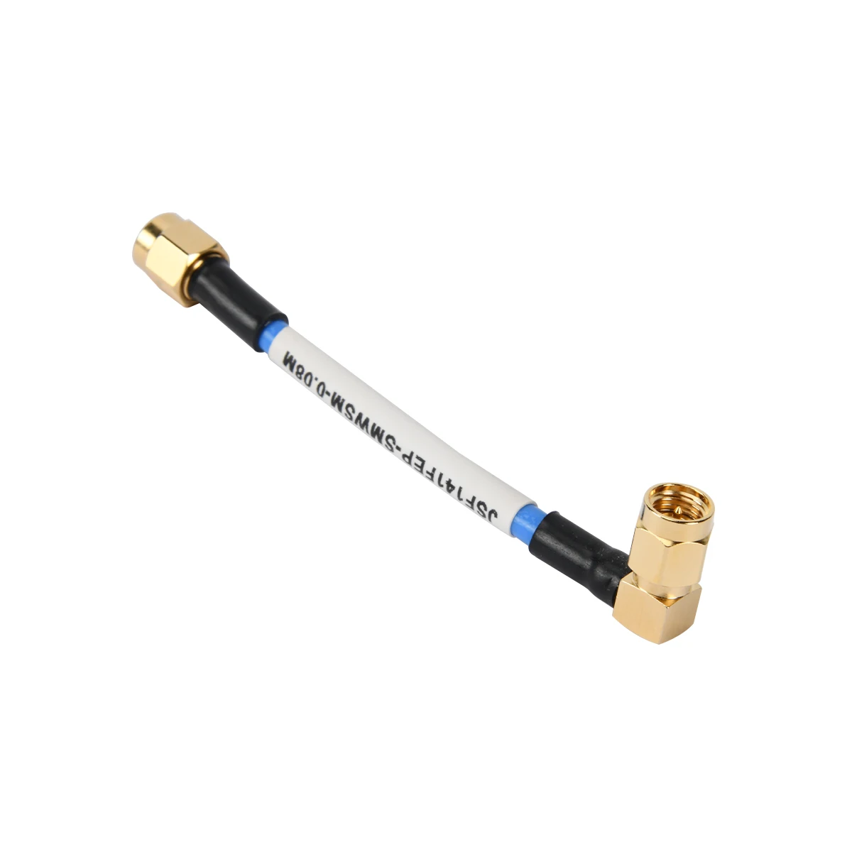
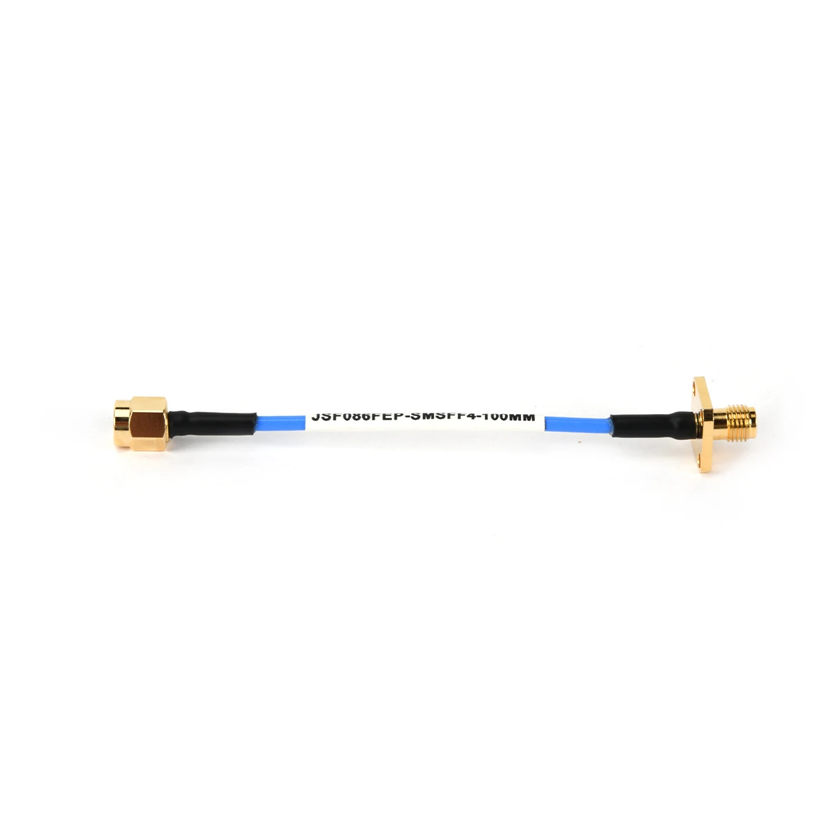
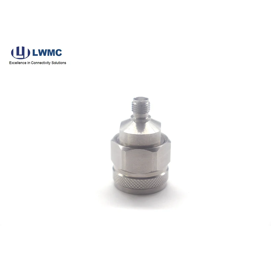
Linkworld’s SMA female connectors are engineered to deliver exceptional electrical performance across DC to 27 GHz, with specialized designs supporting frequencies up to 67 GHz for precision applications. Manufactured in strict compliance with IEC60169 standards, these connectors achieve superior specifications including low voltage standing wave ratio (VSWR) and excellent return loss characteristics. These performance attributes are essential in applications such as radar systems, satellite communications, and high-frequency test instrumentation, where signal integrity directly impacts measurement accuracy and overall system reliability. The female interface design ensures secure mating with standard SMA male connectors, providing consistent electrical contact across repeated connections.
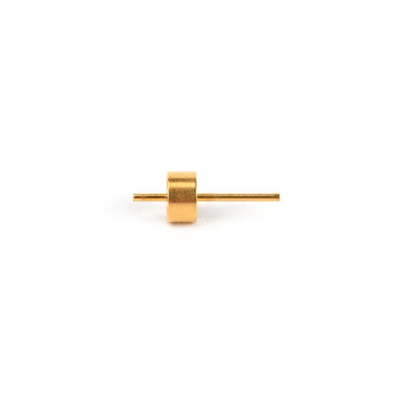
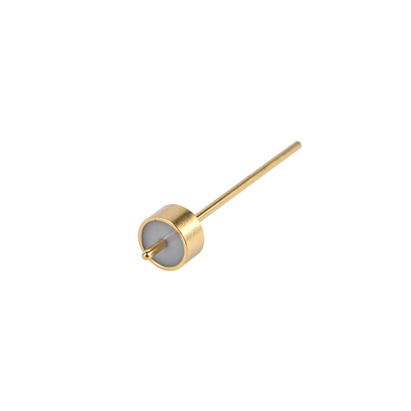
Industrial deployments demand connectors capable of withstanding repeated mating cycles, mechanical vibration, and challenging environmental conditions. Linkworld’s SMA female connectors are constructed with robust materials and precision machining to ensure long-term mechanical stability, with standard products rated for over 500 mating cycles. For applications requiring environmental protection—such as aerospace platforms, military systems, or outdoor telecommunications equipment—our glass seal integration capabilities combine hermetic feedthroughs with SMA female connector assemblies, supporting reliable operation in high-humidity environments and applications demanding protection against contaminants and corrosive elements.
Standard SMA female connector configurations may not fully address the unique demands of specialized industrial systems. Linkworld collaborates closely with customers from the early design phase to develop customized solutions tailored to precise mechanical, electrical, and environmental specifications. With a 25-year experienced R&D team, we excel in high-frequency projects spanning 18 GHz to 67 GHz, particularly in phase-stable and amplitude-stable applications critical to advanced measurement and communication systems. Our end-to-end support encompasses design optimization, prototyping, and post-deployment technical assistance, ensuring seamless integration into customer-specific assemblies.
Linkworld’s SMA female connectors are trusted across industries where connectivity reliability is non-negotiable. Key applications include military and aerospace systems, satellite ground stations, telecommunications infrastructure, test and measurement instrumentation, medical equipment, and radar systems. Guided by the core value of “Honesty and Perfection,” we deliver high-reliability products backed by rigorous quality control, comprehensive testing protocols, and responsive service—enabling industrial clients to maintain operational excellence and system performance across global markets.