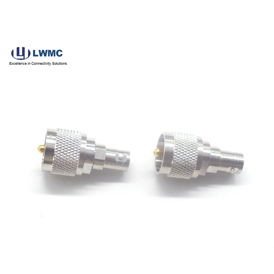
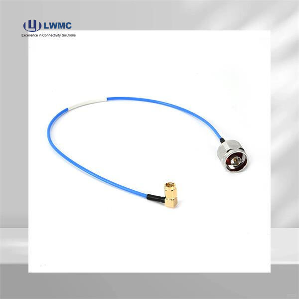
Coaxial cable assemblies are the essential lifelines of modern RF systems, transmitting critical signals with minimal loss and interference. As a core product encompassing RF connectors, adapters, and the cables themselves, a properly built assembly is fundamental to system performance. Whether for a simple test lead or a complex multi-component RF harness, mastering the assembly process ensures reliability in applications from telecommunications to aerospace.
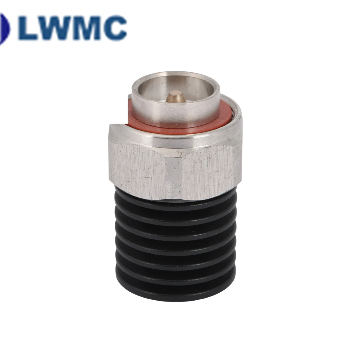
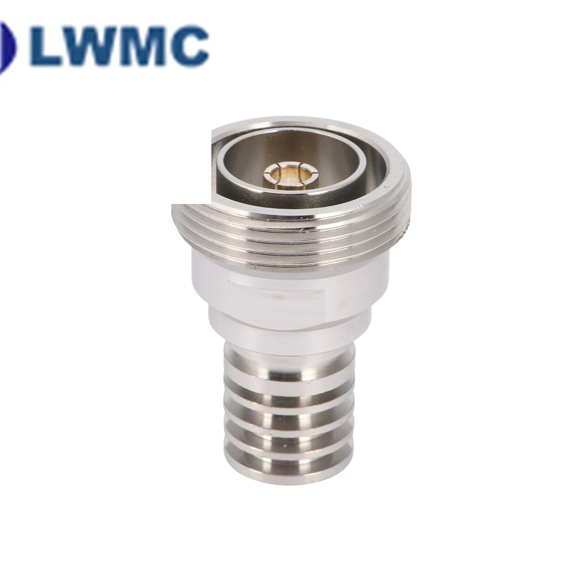
A high-quality coaxial cable assembly is more than just a cable with connectors on each end. Proper assembly is paramount because it directly determines the electrical performance and mechanical durability of the final product. An impeccably assembled cable maintains a consistent impedance (typically 50 or 75 ohms) along its entire length, minimizing signal reflections and Voltage Standing Wave Ratio (VSWR). It ensures optimal shielding integrity, preventing signal leakage and protecting against external electromagnetic interference. Mechanically, a correct assembly can withstand repeated mating cycles, vibration, and pull forces without degradation. In contrast, a poorly assembled cable becomes the weakest link, leading to increased insertion loss, erratic system behavior, and costly downtime.
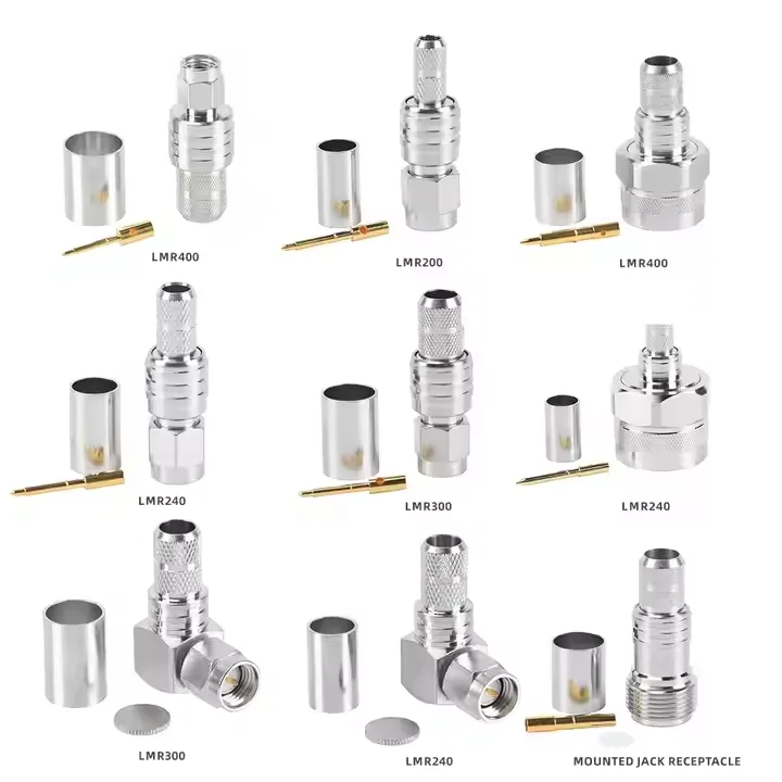
Efficiency comes from precision and consistency. First, always use a dedicated coaxial stripping tool calibrated for your specific cable type (e.g., RG316, LMR-400). This ensures clean, depth-controlled cuts that expose the center conductor, dielectric, and shield braid to the exact lengths required by your chosen RF connector. Second, employ the "dry-fit" method: prepare the cable end and partially assemble the connector without final crimping or soldering to verify all lengths and seating are perfect before making the permanent connection. Third, for crimp-type connectors, use a calibrated crimp tool and visually inspect each crimp for smoothness and uniformity. Finally, keep your work area clean and organized to avoid contamination of the dielectric or center conductor, which can affect performance.
Recognizing and solving assembly flaws is a critical skill. High VSWR or signal loss often points to an impedance discontinuity. Common causes include: a center conductor that is too short or too long (not seated properly in the connector contact), an improperly trimmed dielectric, or a crushed cable from an over-tightened clamp. Intermittent connectivity is frequently due to a poorly secured center contact (a weak solder joint or incomplete crimp) or shield braid that is not making a full 360-degree contact with the connector body. Poor shielding effectiveness results from insufficient braid contact or damaged/under-sized braid ferrule crimps. A simple continuity check with a multimeter and a careful visual inspection under magnification are the first steps in diagnosing these issues.
Investing in the right tools is non-negotiable for professional results. Your core toolkit should include:
Coaxial Cable Stripper: Choose a model adjustable for your specific cable diameters. Precision strippers prevent nicking the center conductor or shield.
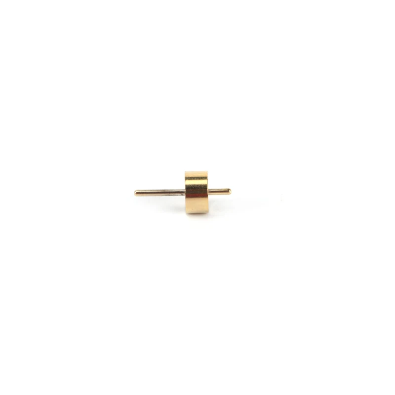
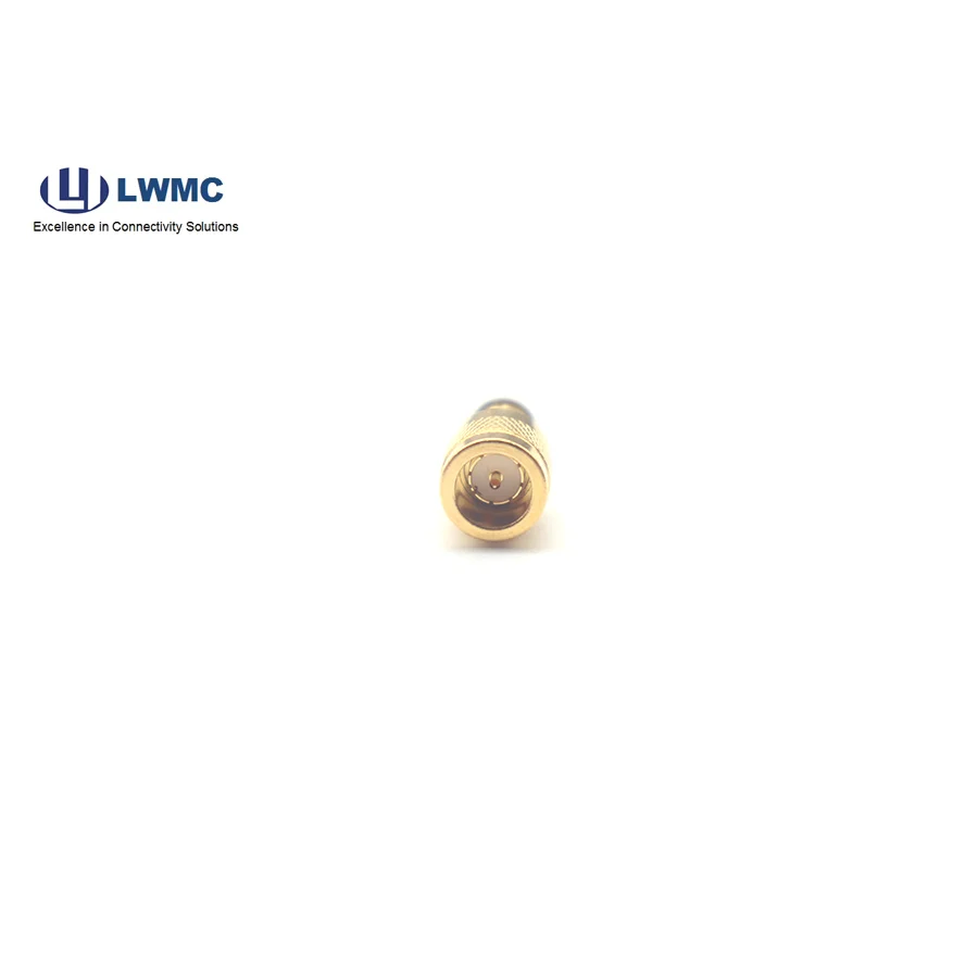
Connector-Specific Crimp Tool and Dies: For crimp-type RF connectors (like SMA, N-Type), a ratcheting, calibrated crimp tool with the correct die sets for the center contact, braid, and outer jacket is essential. Do not use generic crimpers.
Soldering Iron (for solder-type connectors): A temperature-controlled iron with a fine tip is necessary for soldering the center conductor without melting the dielectric.
Torque Wrench: Using a torque wrench to tighten connector nuts (e.g., to 8 in-lbs for SMA) ensures consistent mating force, prevents damage, and guarantees optimal electrical contact.
Inspection & Testing: A jeweler's loupe or magnifier for visual inspection and basic testing equipment like a multimeter and a VSWR bridge or network analyzer for performance verification.