The combination of an N connector and RG58 coaxial cable forms a classic and widely deployed RF solution, balancing performance, durability, and cost-effectiveness for numerous applications. This pairing is a cornerstone in professional and commercial radio systems, test equipment setups, and general-purpose signal distribution. The N connector’s robust threaded interface provides superior mechanical stability and weather resistance, while the flexible RG58 cable offers practical manageability. Understanding the proper installation, comparative advantages, selection criteria, and maintenance of N connector RG58 assemblies is essential for ensuring optimal signal integrity and long-term system reliability across diverse operating environments.
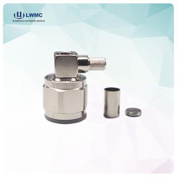
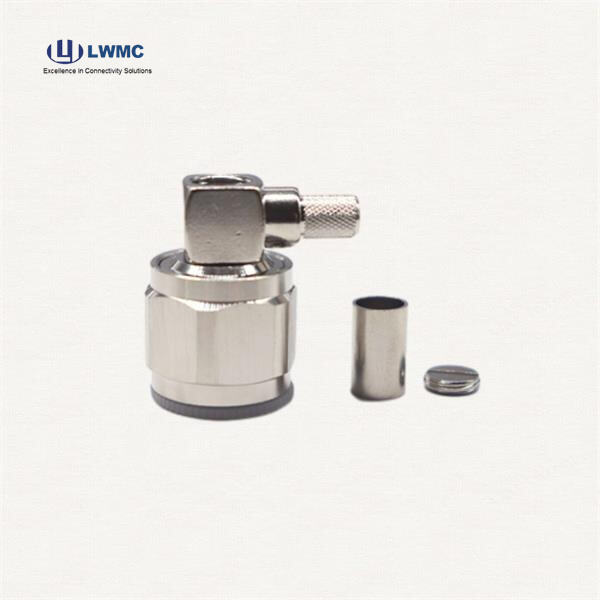
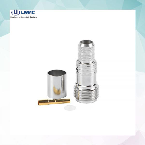
Achieving maximum signal strength and minimum loss with an N connector on RG58 cable requires meticulous installation. The process begins with precise cable preparation using a coaxial stripping tool to remove the outer jacket, braid, and dielectric to exact lengths specified by the connector manufacturer, taking care not to nick the center conductor. For a standard crimp-type N connector, the prepared cable is inserted so the center conductor seats fully into the connector’s contact pin, while the braid is flared over the cable jacket. A two-step crimping process is then critical: first, a center contact crimp secures the conductor, followed by a ferrule crimp that compresses the braid and outer jacket, creating a secure mechanical bond and excellent electrical continuity for the shield. Finally, the coupling nut is assembled. Proper tooling and adherence to specifications are paramount to ensure a low VSWR connection that preserves signal strength.
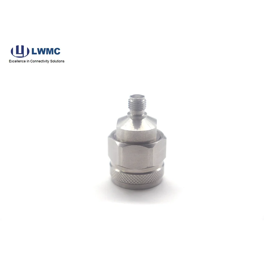
RG58 cable with an N connector serves a specific niche within the broader RF landscape. Compared to thicker cables like LMR-400 or RG213, RG58 has higher signal attenuation (approximately 24 dB/100ft at 1 GHz), making it less suitable for long feeder runs but excellent for shorter interconnects and jumpers due to its flexibility. Against smaller cables like RG174, RG58 offers lower loss and better durability. The choice of the N connector itself is also significant. Compared to BNC connectors (common on RG58), the N connector provides a weather-sealed, vibration-resistant threaded interface superior for outdoor or high-vibration environments. Versus UHF connectors, the N type offers better performance at frequencies above 300 MHz. This makes the N connector RG58 assembly ideal for applications requiring a robust interface on a flexible, general-purpose cable for runs under 50 feet.
Selecting the correct N connector RG58 assembly is crucial for project success. Key considerations include:
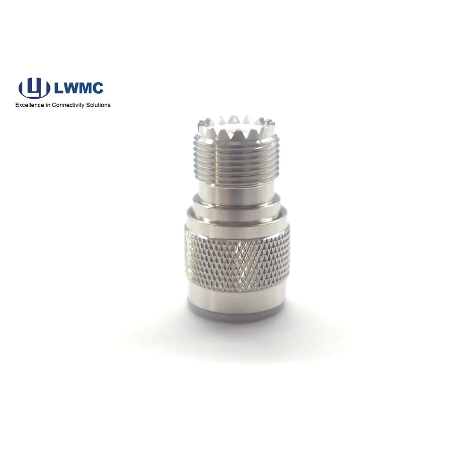
Connector Gender and Polarity: Ensuring the assembly has the correct male or female interface to mate with your equipment.
Cable Length and Loss Budget: Calculating total system attenuation to ensure RG58’s loss over the required distance is acceptable for your application (common in mobile installations, test benches, or short antenna leads).
Environmental Requirements: Specifying connectors with neoprene gaskets or O-rings for outdoor use, and considering additional weatherproofing.
Termination Quality: Deciding between a field-installable connector kit or a factory-pre-terminated assembly. For guaranteed performance, a factory-made assembly from a manufacturer like Linkworld ensures precise, tested terminations with optimal VSWR, saving time and eliminating installation variables.
Matching the assembly to the electrical, mechanical, and environmental demands of the application prevents performance degradation and premature failure.
Common issues with N connector RG58 assemblies often stem from installation errors or environmental wear. Key problems and solutions include:
High VSWR/Poor Signal: This is frequently caused by a poor center conductor connection, an improper braid ground, or cable damage. Re-terminate the connector using the correct procedure and tools, or replace the assembly.
Intermittent Connection: Often due to a loose coupling nut or corrosion on the mating surfaces. Tighten the connection and clean contacts with electronic-grade cleaner. Inspect the connector pin and socket for physical damage.
Water Ingress: If moisture is found, the environmental seal has failed. Ensure the connector’s rear rubber grommet is properly seated and the coupling nut is fully tightened. For permanent outdoor fixes, apply a layer of waterproof sealing tape over the connector interface.
Connector Difficult to Mate: Check for cross-threading, dirt, or deformation. Never force the connection. Ensure you are using compatible N types (not mixing 50-ohm and 75-ohm versions by mistake).