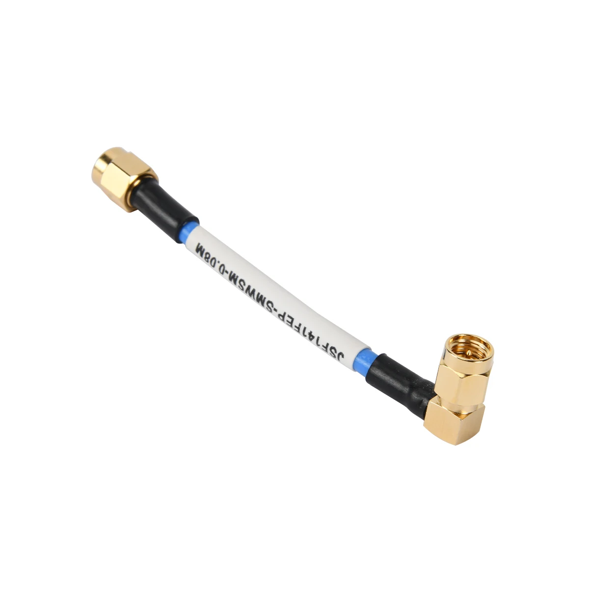
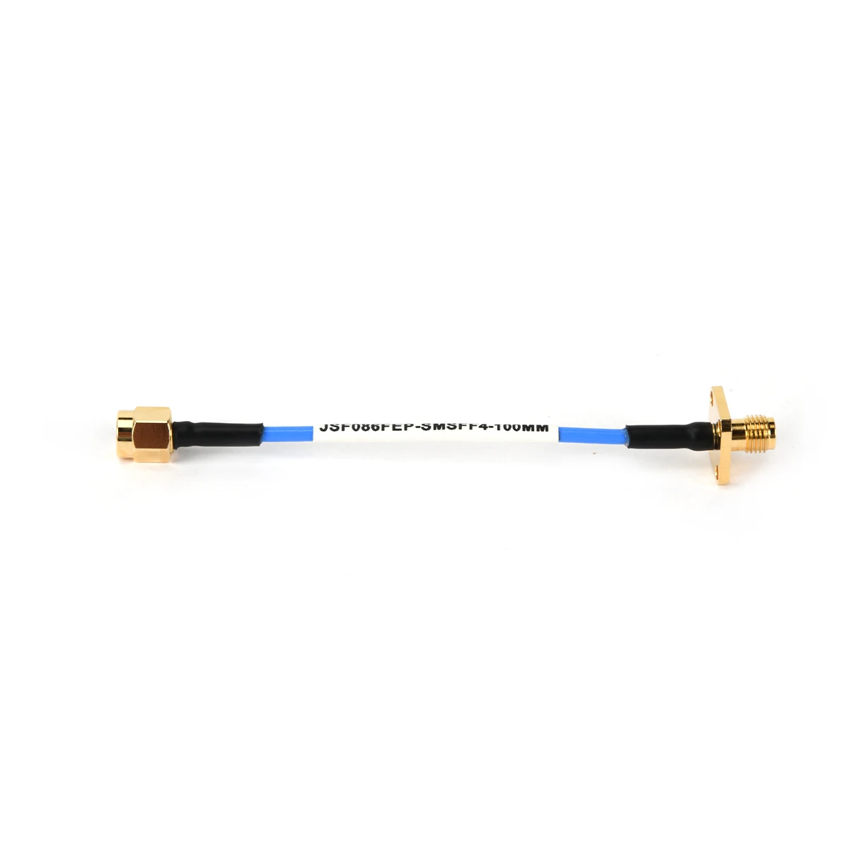
In the realm of radio frequency (RF) systems, reliable signal transmission hinges on one fundamental partnership: the Male Connector and Female Connector. This mating pair forms the essential interface for all RF Connectors, Coaxial Cable Assemblies, and RF Adapters. Understanding how to identify, choose, and maintain these connections is critical for ensuring optimal performance and preventing costly signal degradation or system failure.
In RF terminology, gender is defined by the center contact, not the outer coupling mechanism. This is a crucial distinction from some other electrical fields.
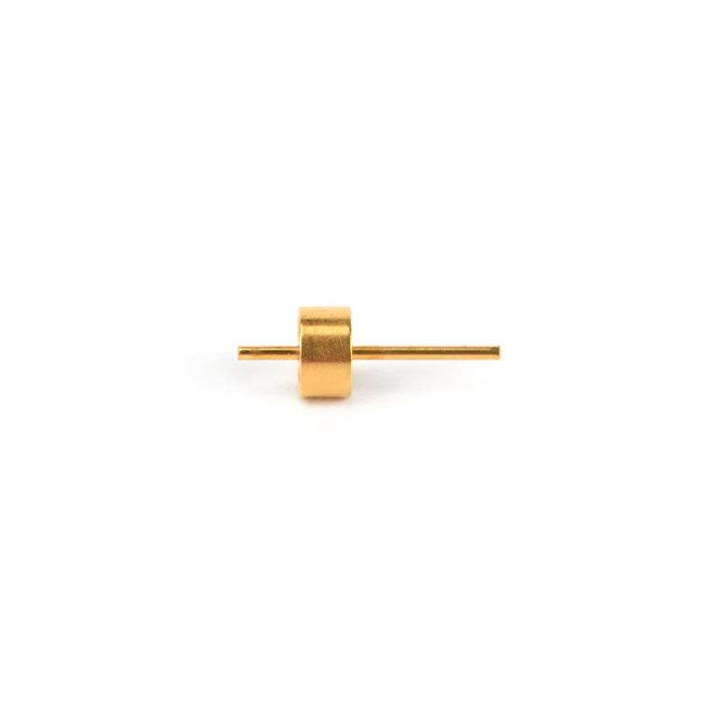
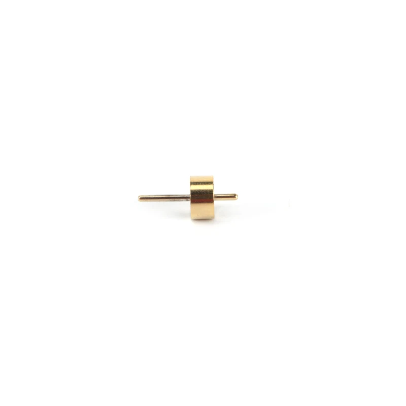
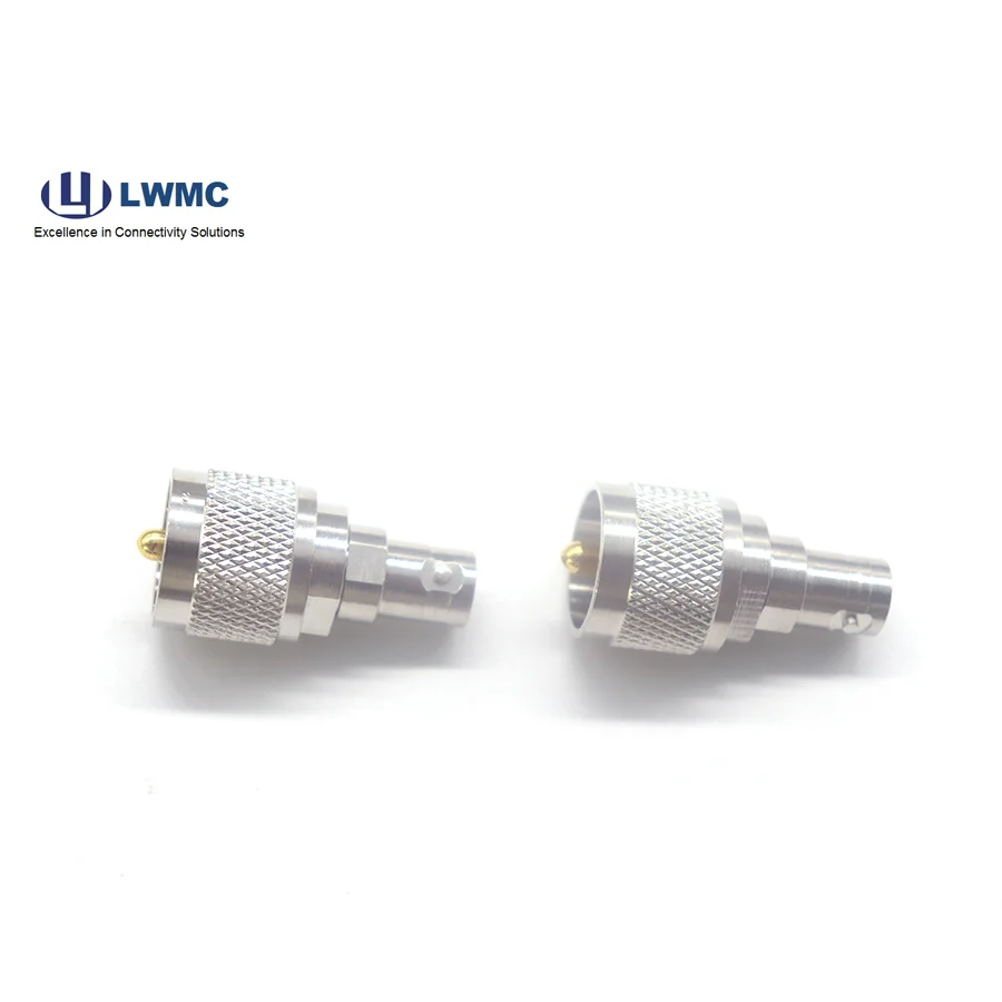
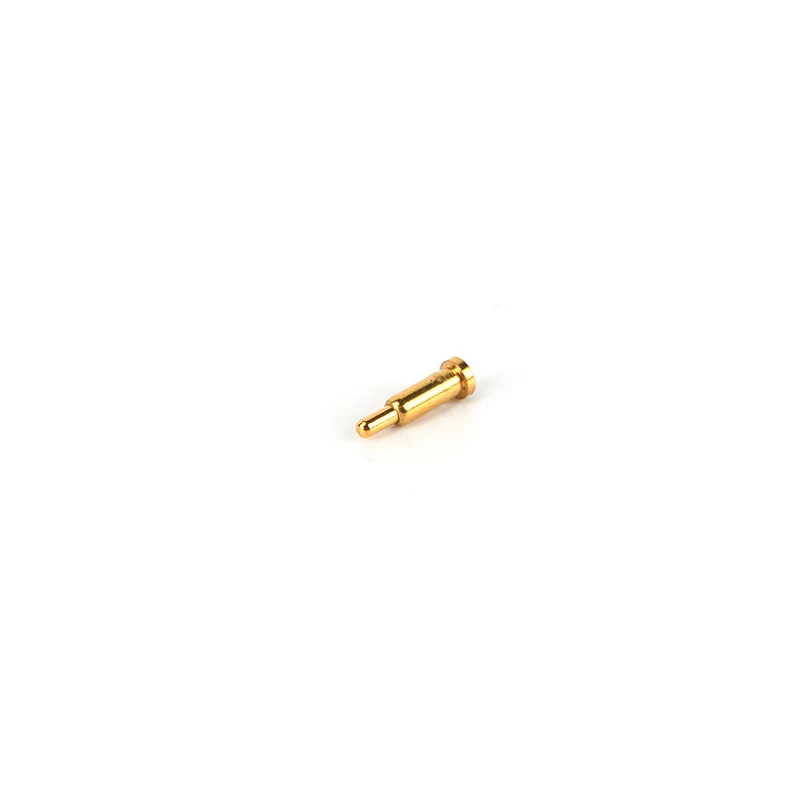
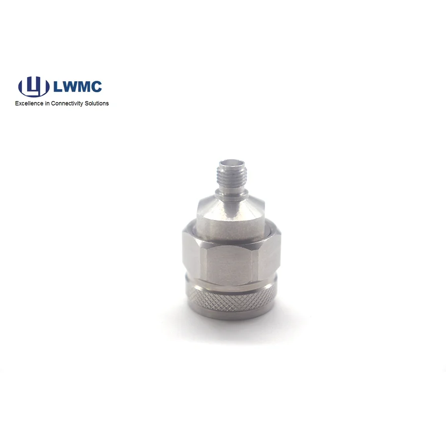
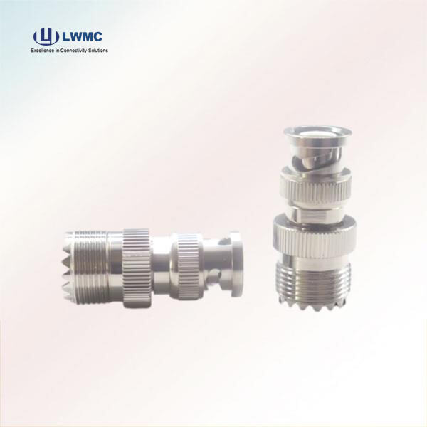
Male Connector (Plug): Characterized by a protruding center pin. The outer shell typically has internal threads.
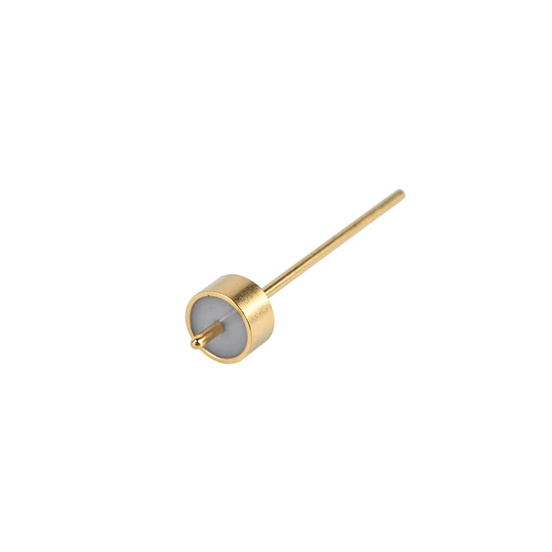
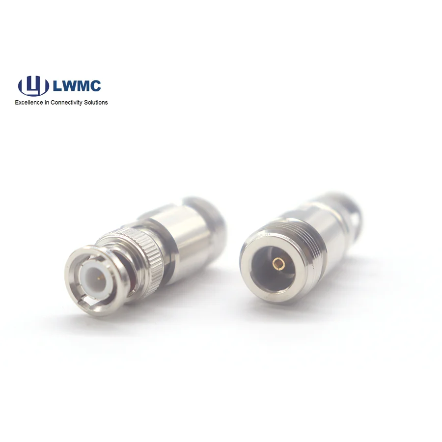
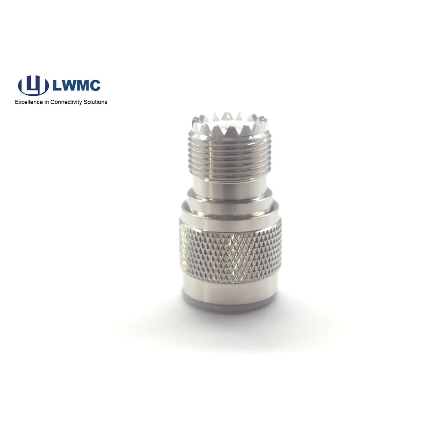
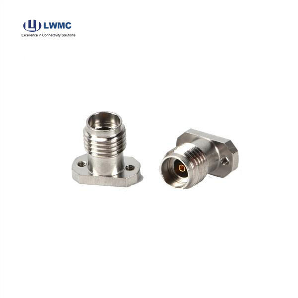
Female Connector (Jack): Characterized by a recessed center socket designed to receive the male pin. The outer shell usually has external threads.
A simple rule: The pin is in. If the center contact sticks out, it's male. If it is a hollow socket, it's female. This holds true for all common RF series like SMA, N-Type, TNC, and BNC (though BNC uses a bayonet coupling instead of threads).
Selecting the right pair goes beyond just matching genders. A correct match ensures mechanical compatibility and electrical performance.
Series/Type Must Match: An SMA male connector can only properly mate with an SMA female connector. Forcing dissimilar series (e.g., SMA male to N female) requires the correct RF Adapter.
Impedance Must Match: Almost all RF systems use 50-ohm connectors. Mating a 50-ohm connector with a 75-ohm one (common in video) will cause significant signal reflection and loss.
Performance Specifications: For high-frequency applications, ensure both connectors are rated for the required frequency range (e.g., up to 18 GHz for SMA). Material quality (e.g., gold plating) also affects loss and durability.
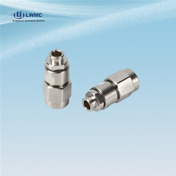
Application Context: Coaxial Cable Assemblies are typically terminated with a male and female connector pair. RF Adapters often combine male and female ends of the same or different series to solve specific interface problems.
A loose connection increases resistance, causes signal intermittency, and elevates VSWR.
Check for Under-Tightening: For threaded connectors (SMA, N), ensure they are torqued to the manufacturer's specification using a proper wrench. Hand-tight may not be sufficient.
Inspect for Wear: Over many mating cycles, the female socket can become slightly widened, and the male pin can wear down, reducing grip. Inspect for visible damage. The only permanent fix for significant wear is replacement of the connector or cable assembly.
Examine Coupling Mechanisms: For bayonet-style (BNC), ensure the pin is fully inserted and rotated until it clicks and locks. For snap-on (SMB), check that the spring mechanism is not damaged.
Check Adapter Integrity: If the connection involves an RF Adapter, ensure the adapter itself is not the source of the looseness.
A reliable connection is secure, electrically sound, and long-lasting. Follow this checklist:
Cleanliness: Before mating, inspect and clean both contacts with compressed air and isopropyl alcohol. Even tiny debris can impede signal flow.
Proper Alignment & Threading: Always align connectors straight on and start threading by hand to prevent cross-threading, which can destroy the threads instantly.
Use Correct Torque: Employ a calibrated torque wrench for threaded connectors. This applies the perfect pressure for optimal electrical contact without damaging the threads or dielectric.
Strain Relief: For cable connections, use proper strain relief boots or clamps to prevent bending force from being transferred to the connector neck, which can break the solder or crimp joint inside.
Use Protection: Always install protective dust caps on unmated connectors to prevent physical damage and contamination of the critical center contacts.