In the intricate world of radio frequency (RF) systems, seamless connectivity is paramount. When direct connections are impossible due to mismatched interfaces or gender conflicts, a simple yet powerful component comes to the rescue: the Male Adapter. Often overlooked, these specialized RF Adapters are indispensable tools for engineers and technicians working with RF Connectors and Coaxial Cable Assemblies. They serve as the essential bridge, enabling flexibility and functionality across diverse applications.
A Male Adapter is defined by having male threads (a protruding center pin) on at least one of its ends. Its primary function is to convert a female port into a male connection point. Common applications include:
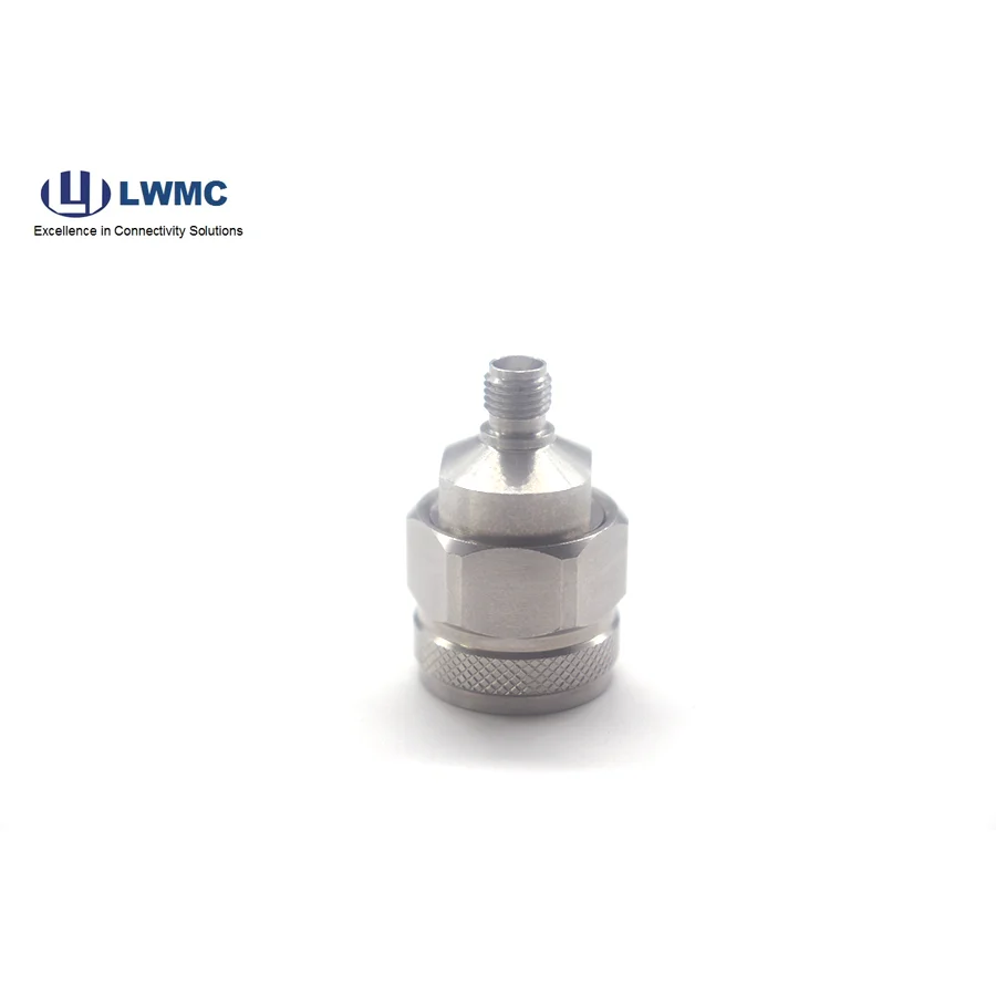
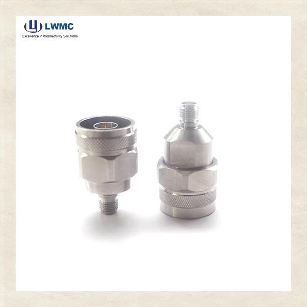
Connecting Test Equipment: Attach an SMA Male to N Male adapter to connect a cable with an N-type end to a vector network analyzer with an SMA female port.
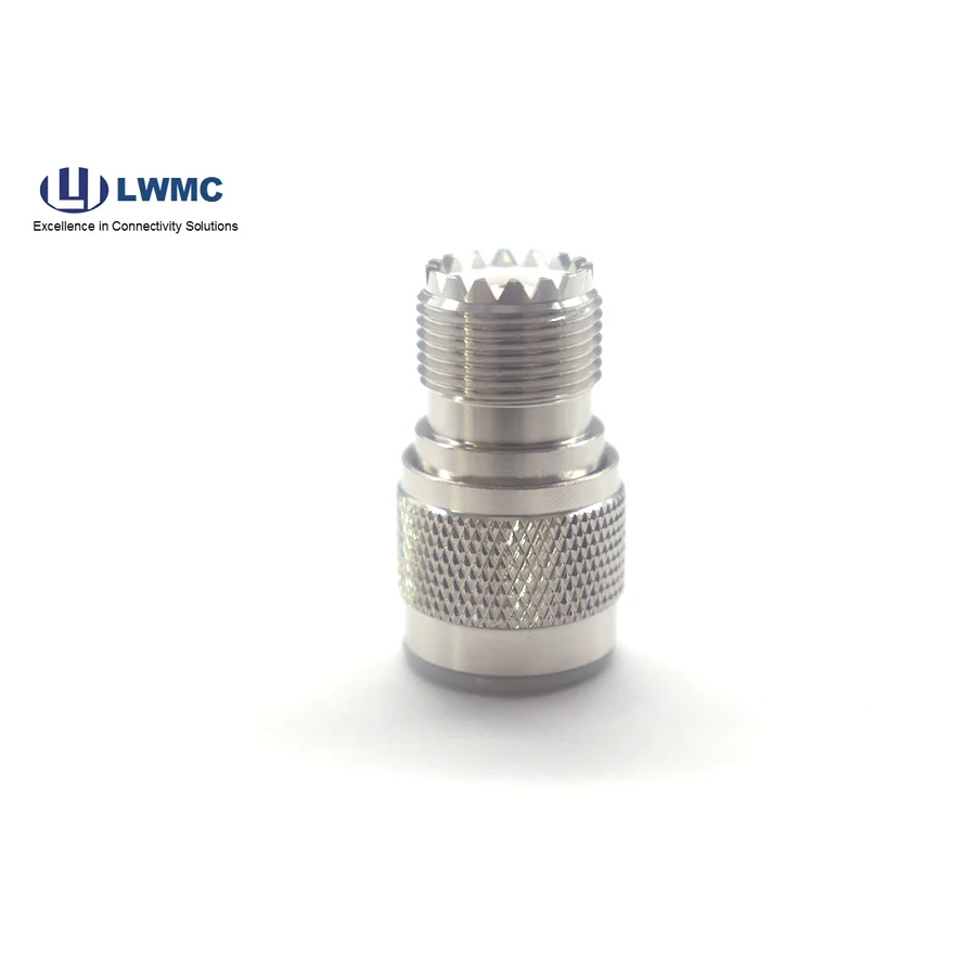
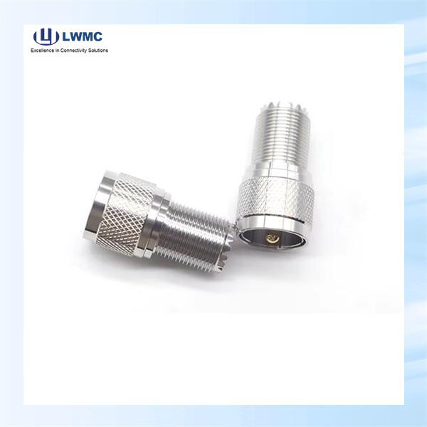
Extending Cable Runs: Use two adapters (e.g., N Male to N Female) to join two cable assemblies with male connectors.
Converting Genders and Series: A Male Adapter can solve a simple gender change (e.g., BNC Female to BNC Male) or a more complex between-series conversion (e.g., 7/16 Male to N Female), allowing interconnection of different equipment standards.
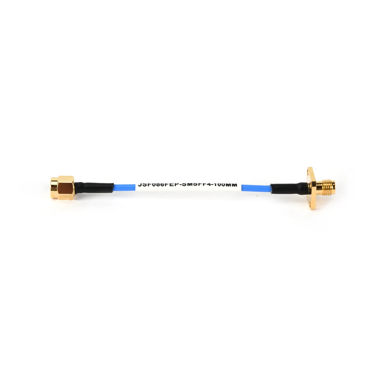
Panel Mounting: While not a panel mount itself, a Male Adapter can be used with a female bulkhead connector to bring a male interface through a chassis wall.
System Flexibility: They provide an economical and immediate solution to interface mismatches without requiring custom Coaxial Cable Assemblies.
Inventory Management: Technicians can maintain a stock of standard cables and use a set of adapters to cover numerous connection scenarios, reducing the need for countless specialized cables.
Troubleshooting and Testing: Adapters are crucial for connecting diagnostic equipment to various points in an RF system, enabling signal testing and fault isolation.
Preserving Equipment: They protect expensive equipment ports from wear and tear caused by frequent direct cable mating; the adapter becomes the sacrificial interface.
Selecting the correct adapter is critical to maintain signal integrity. Follow these key criteria:
Interface Types: Precisely identify the connector series (SMA, N, TNC, etc.) and gender you need to connect from and to (e.g., "SMA Female to N Male").
Frequency Rating: Ensure the adapter's specified frequency range meets or exceeds your application's requirements. A 6 GHz adapter will fail in an 18 GHz system.
Impedance: Match the system impedance, almost always 50 ohms for telecommunications (or 75 ohms for video/broadcast).
Material and Plating: Choose brass or stainless-steel bodies with gold or silver plating for low-loss, high-frequency, or corrosion-resistant applications.
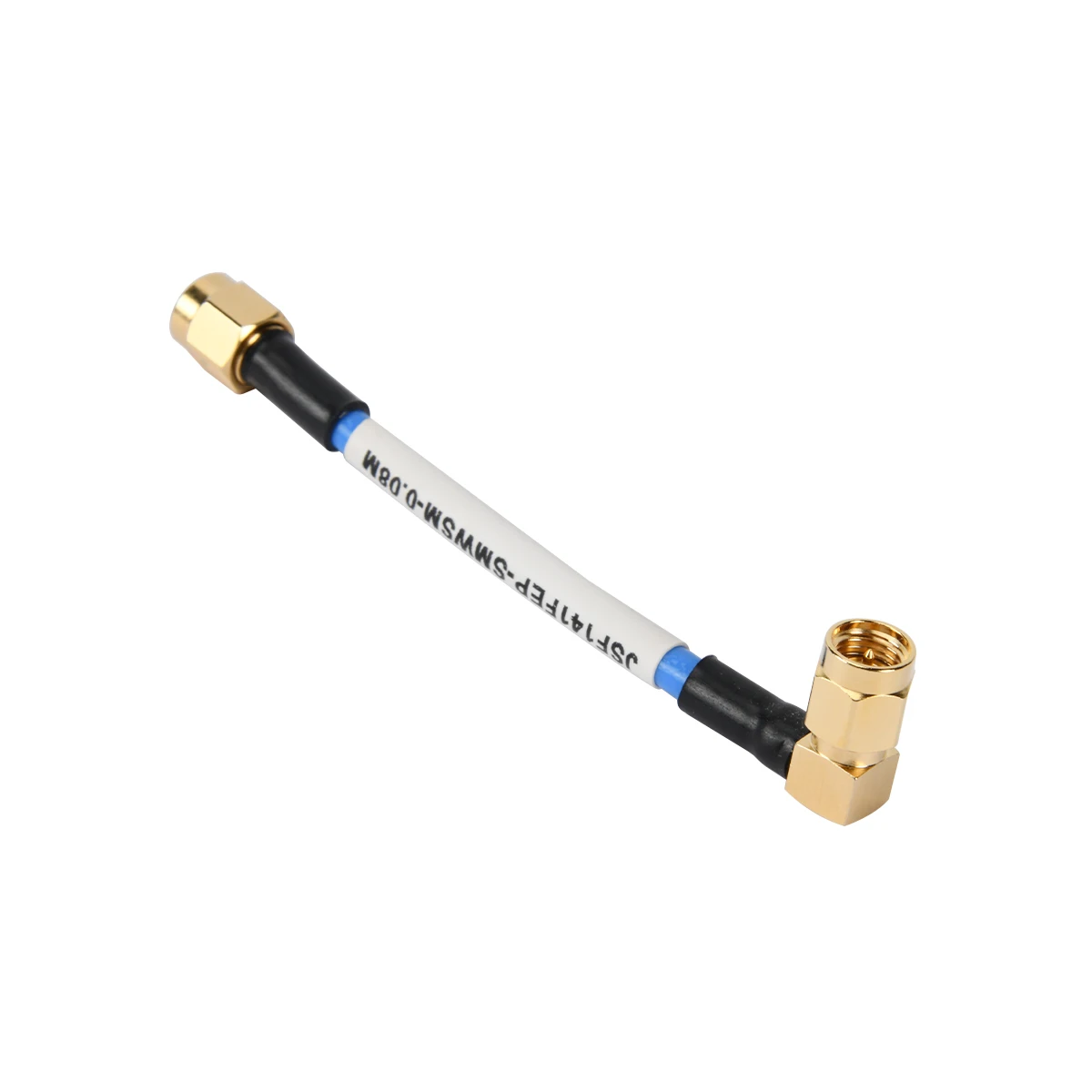
Configuration: Decide between straight, right-angle, or bulkhead designs based on spatial constraints.
Improper installation can introduce signal loss, reflection, and damage.
Inspect First: Check for bent pins, debris, or damaged threads on both the adapter and the target port.
The Hand-Tighten Rule: Always start threading by hand to ensure perfect alignment and avoid cross-threading, which can ruin both components instantly.
Use Proper Torque: After hand-tightening, use a calibrated torque wrench to tighten to the manufacturer's specification. This ensures optimal electrical contact without over-compressing and damaging the connectors.
Minimize Interconnects: While adapters are invaluable, each one introduces a small discontinuity. For critical, high-frequency paths, minimize the number of adapters in line, preferring a direct cable assembly where possible.
Path Consideration: In a chain of connections, install the adapter onto the more robust, stationary port first (like equipment), then connect the cable to the adapter.