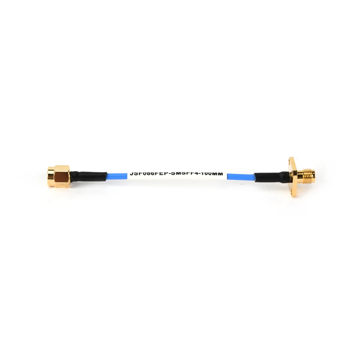
In the world of RF engineering, the seamless transmission of high-frequency signals depends on a core partnership: the precise mating of the female and male connector. These are not mere plugs and sockets; they are precision-engineered interfaces that form the backbone of every Coaxial Cable Assembly and RF Adapter. Proper management of this pairing is critical to the performance and reliability of any system involving RF Connectors.
Proper matching is the first principle of RF connectivity. A correct match ensures three key outcomes: mechanical integrity, electrical performance, and signal integrity. Mechanically, mating the correct series and gender prevents physical damage, such as bent pins or stripped threads. Electrically, it maintains the designed 50-ohm impedance path (standard for most RF systems), minimizing signal reflections measured as Voltage Standing Wave Ratio (VSWR). An improper match, like forcing dissimilar connectors together or using a 75-ohm connector in a 50-ohm system, creates discontinuities. These discontinuities cause signal loss, distortion, and potential system failure, compromising everything from data throughput in telecommunications to measurement accuracy in test labs.
Safety in RF connections pertains to both equipment protection and personnel. Always begin with a visual inspection. Check the male center pin for straightness and the female socket for debris or damage. Before coupling, ensure the connectors are from the same series (e.g., both are N-type). Align them carefully and start threading by hand—never force the connection. This prevents cross-threading, which can permanently ruin expensive connectors. Once hand-tight, use a calibrated torque wrench to achieve the manufacturer's specified tightening value. This step is non-negotiable for secure, gas-tight connections that ensure optimal electrical contact without damaging the delicate internal dielectric. For disconnection, always grip the connector body, not the cable or adapter.
The RF industry offers a vast ecosystem of standardized connector pairs to suit every application. Common series include:
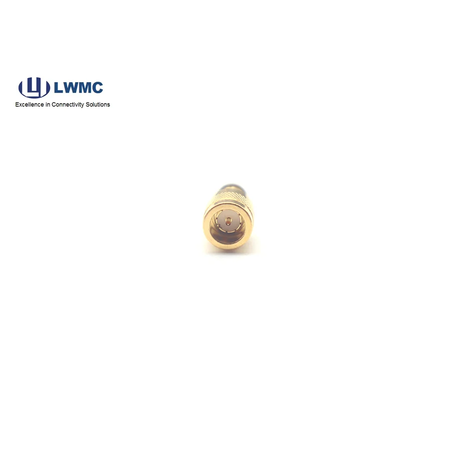
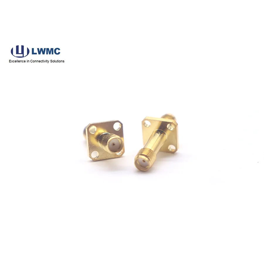
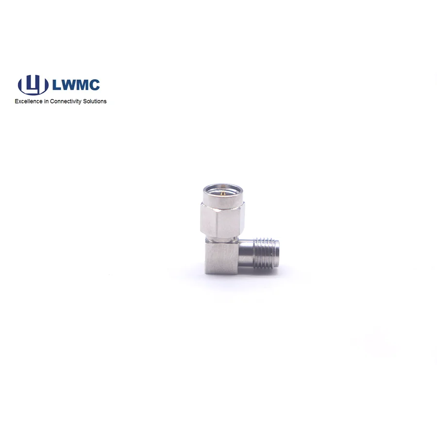
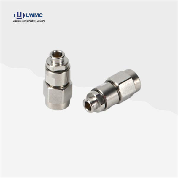
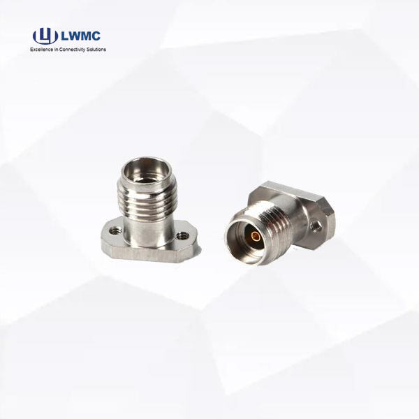
SMA (SubMiniature version A): A threaded, semi-precision connector ubiquitous in applications up to 18-26.5 GHz, common in internal electronics and antennas.
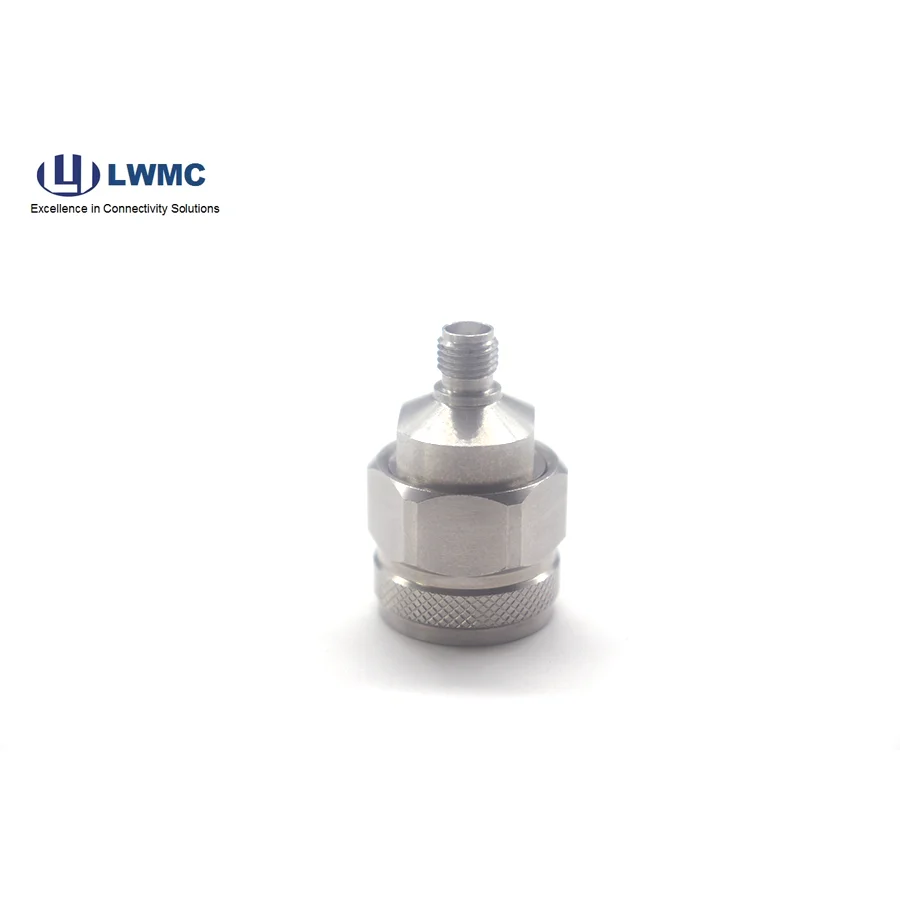
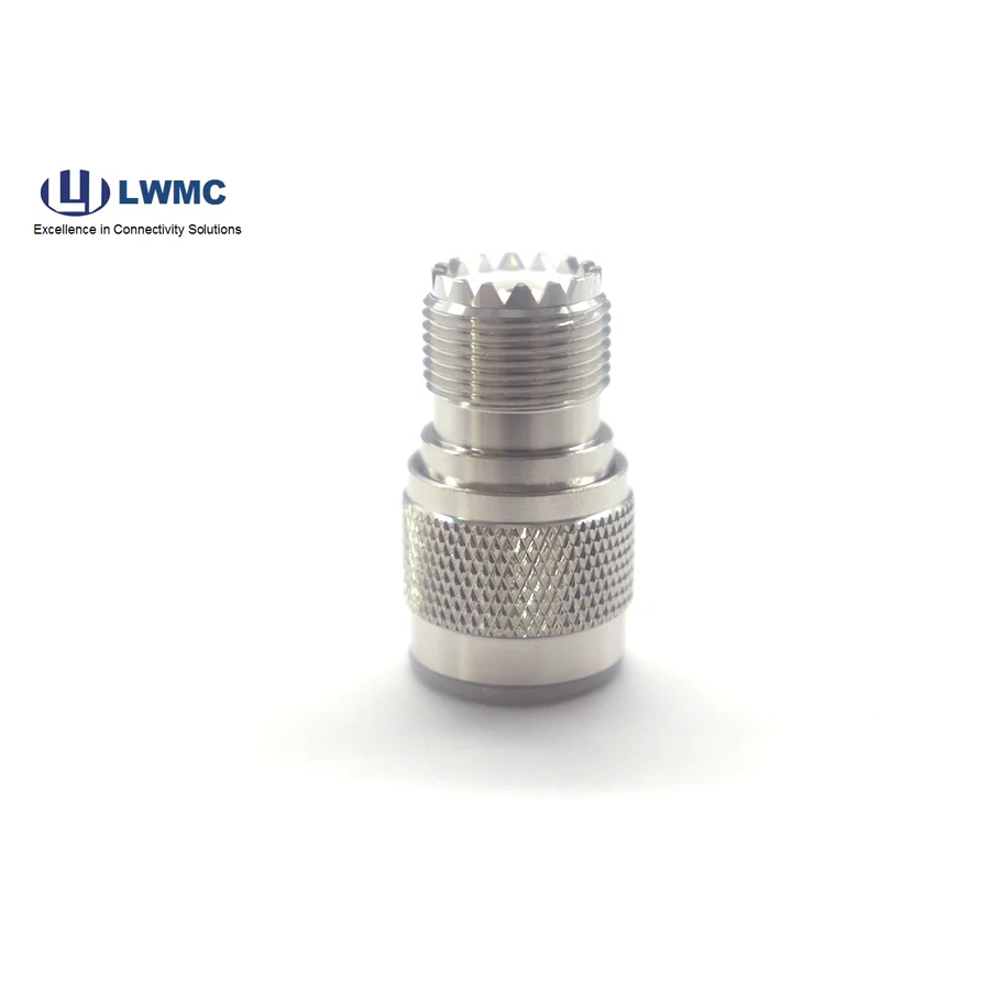
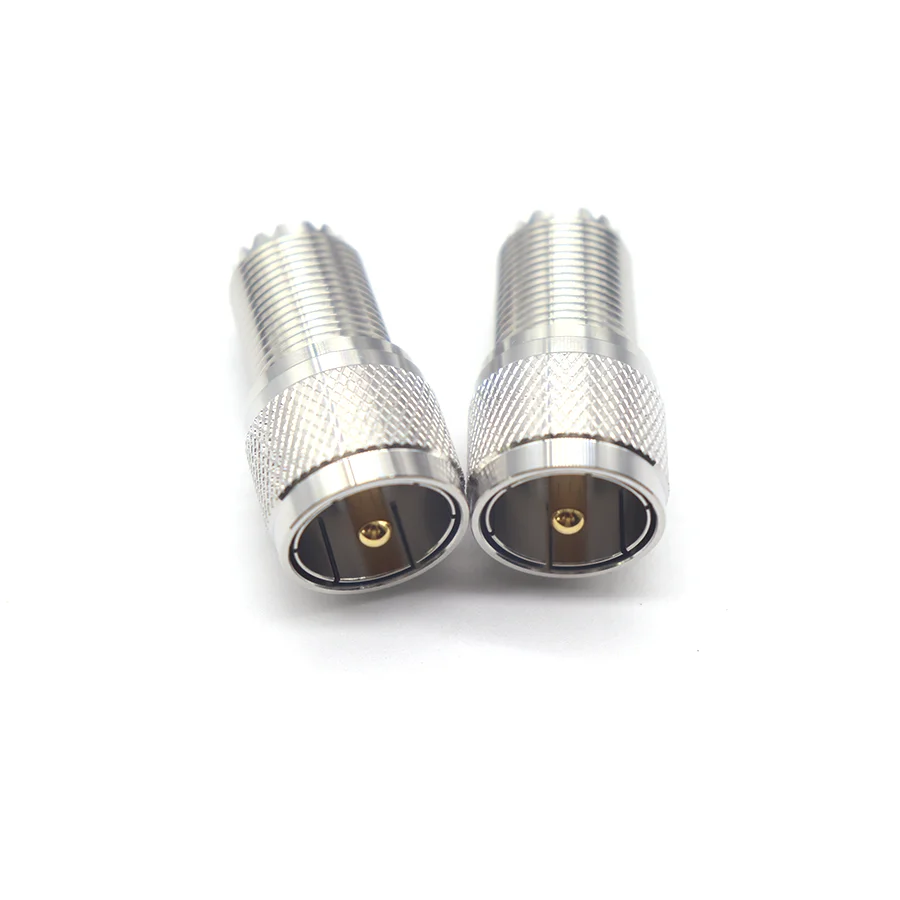
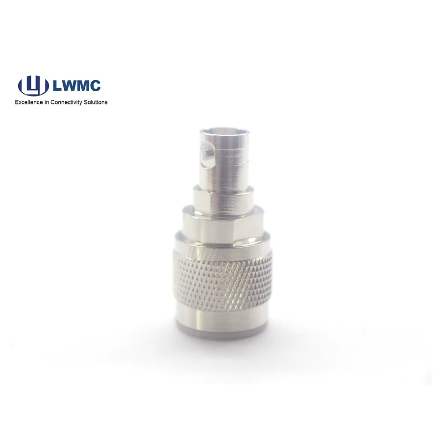
N-Type: A larger, threaded connector known for robustness, weatherproofing, and excellent performance up to 11 GHz, widely used in infrastructure.
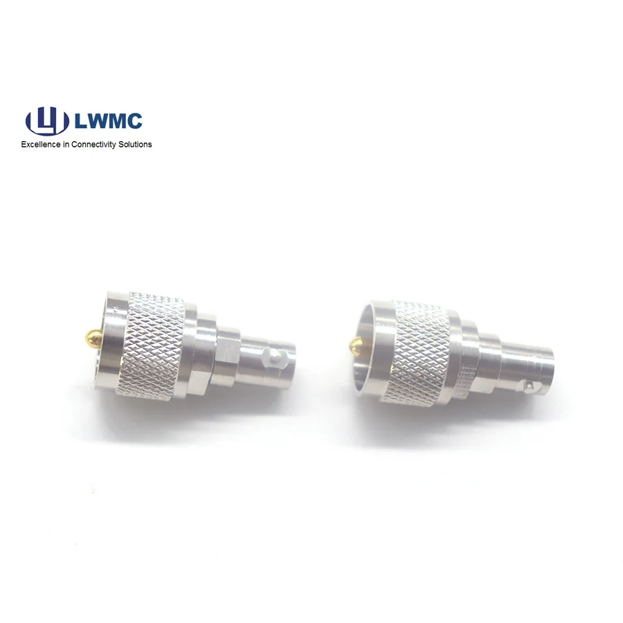
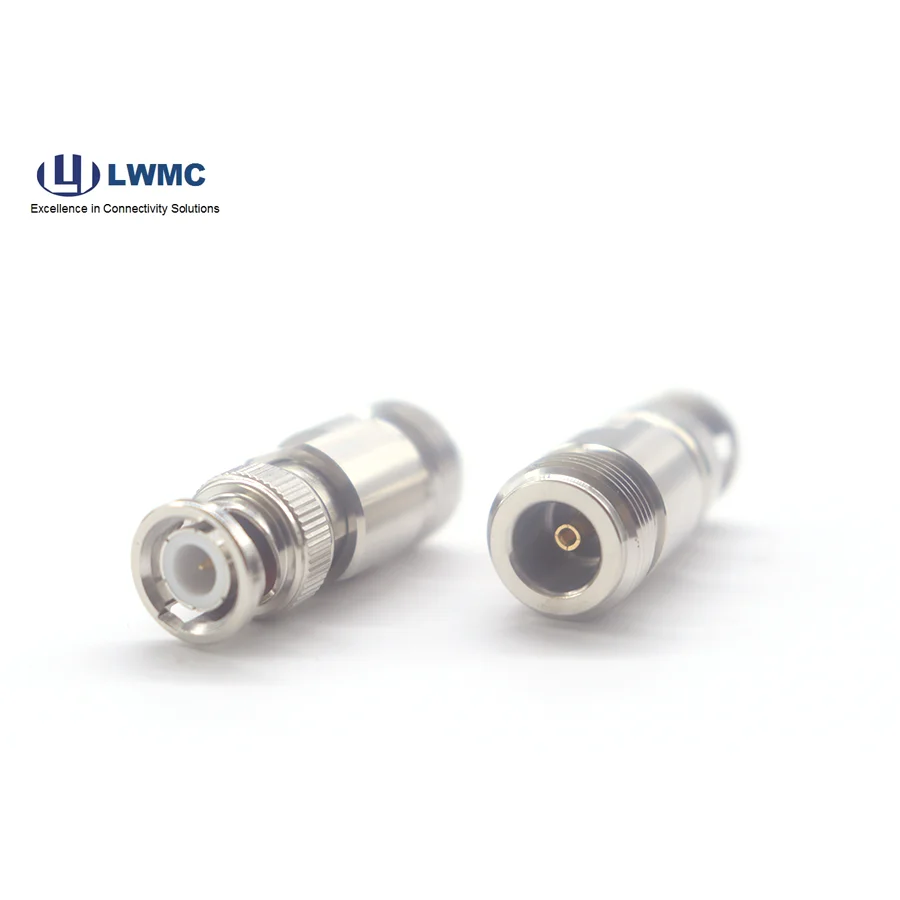
BNC: A bayonet-style connector for quick connect/disconnect, common in test equipment and lower-frequency applications (up to 4 GHz).
7/16 DIN: A large, threaded connector designed for high-power transmission with very low passive intermodulation (PIM), used in cellular base stations.
RF Adapters further expand this variety, enabling connections between different series (e.g., SMA male to N female) or solving gender challenges within the same series.
Most connector problems manifest as poor signal quality or intermittent connections.
High VSWR/Signal Loss: The most common culprit is a dirty or damaged interface. Clean contacts with isopropyl alcohol and compressed air. Inspect for a dented female socket or a bent male pin.
Intermittent Connection: Often caused by a loose coupling, a worn-out female contact, or internal cable failure near the connector. Re-torque the connection and inspect for wear. Gently wiggle the cable while monitoring the signal to check for a cable fault.
Difficulty Mating: If connectors won't start threading, confirm they are the same series. If they seize during tightening, they are likely cross-threaded—do not force them, as this will compound the damage.
Water Ingress: For outdoor connections, failure to properly seal mated connectors (using sealing tape or rubber boots) can lead to corrosion and failure. Always use weatherproof versions or seals for exterior applications.